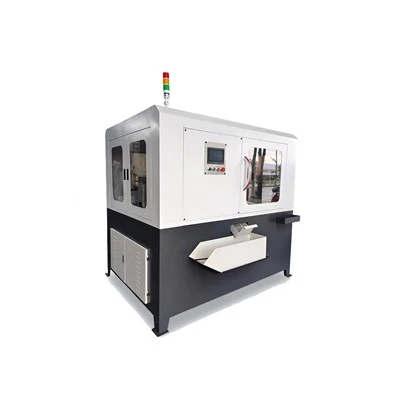
Product Overview
The Automatic Loading and Unloading Machine is a powered handling and feeding system that moves raw workpieces into CNC lathes, machining centers or drilling machines and removes completed parts. It is used in production cells handling bars, discs, rings and individually fixtured metal components.
Key Features
Five Load Ratings for Different Workpieces
The available handling capacities are 5, 15, 30, 50 and 100 kg. For a lightweight bearing ring with a short machining cycle, a lower-payload head avoids unnecessary moving mass; heavier blanks are assigned to the reinforced handling models so the carrier matches the actual gripping load.
Gripping Heads Matched to Part Geometry
Pneumatic fingers locate regular shapes, three-jaw chucks center round bar sections, and vacuum cups pick up flat plates or discs. For suction-based handling, the cup layout is designed with a 2× safety margin. This avoids using the same contact geometry for a machined ring and a flat-faced blank.
Travel Ranges for Machines with Different Loading Heights
Depending on load class, the X-axis spans 800–3000 mm and Z-axis lifting travel covers 400–1000 mm. Where a feeder stands away from the enclosure and the chuck is inside a guarded machine, the vertical and horizontal stroke combination reaches both locations along the planned approach path.
Handling Cycle Matched to Part Weight
Published loading cycles range from 6–10 seconds on light-duty units, 8–12 seconds on medium-duty units and 10–15 seconds on heavy-duty units. On a machine that finishes a cut every few seconds, the handling model can be chosen against the available load/unload window rather than only the maximum workpiece weight.
Custom Automatic Loading and Unloading Machine
The loading cell is laid out from the blank dimensions, part orientation, machine door and chuck details, feeder position and cutting cycle. We configure the gripper, strokes and storage presentation method to match the part flow, then connect the transfer sequence to the host machine signals.
Customizable Items
• Maximum blank weight
• X-axis transfer length
• Z-axis lifting height
• Pneumatic / chuck / vacuum gripping
• Part-contact finger geometry
• Bar stock magazine
• Disc stacking arrangement
• Infeed and outfeed positions
• Part orientation at spindle
• Door / chuck signal interface
• Loading cycle sequence

Technical Parameters
|
Parameter |
Light-Duty |
Medium-Duty |
Heavy-Duty |
|
Max. Gripping Weight (kg) |
5 / 15 |
30 / 50 |
100 |
|
X-axis Travel (mm) |
800 ~ 2000 |
1000 ~ 2500 |
1500 ~ 3000 |
|
Z-axis Lift Travel (mm) |
400 ~ 600 |
600 ~ 800 |
800 ~ 1000 |
|
Cycle Time (s) |
6 ~ 10 |
8 ~ 12 |
10 ~ 15 |
|
Gripping Method |
Pneumatic Fingers / Suction Cup |
Fingers / Chuck / Suction Cup |
Chuck / Suction Cup |
|
Bar Feeder Length (mm) |
500 ~ 1000 |
500 ~ 1500 |
500 ~ 1500 |
|
Disc Stack Height (mm) |
200 |
300 |
300 |
|
Positioning Accuracy (mm) |
±0.03 |
±0.03 |
±0.03 |
|
Suitable Machines |
CNC Lathes / Drilling Machines |
CNC Lathes / Machining Centers |
Machining Centers / Gantry Mills |
Quality Control
Guideways, gripping actuators, feeding mounts and machine-side locating points are inspected during assembly. Self-inspection is performed after each fitting operation, followed by cross-checks at the interfaces where the machine tool and handling equipment meet.
Commissioning runs the blank-to-chuck and chuck-to-outfeed sequences with attention to gripping, release and correct positioning. The programmed motion is checked around the door opening and chuck approach to verify that transfers occur only through the intended machine-ready sequence.
Before shipment, the complete loading unit passes a full operating and appearance inspection. The machine is then secured in export protection, and a third-party inspector may witness the final acceptance checks.
FAQ
Q: What is the lead time for a custom loading system?
A: Approximately 2 months.
Q: How is it packed for export?
A: A wooden shipping case.
Q: What bar lengths can the feeder hold?
A: 500–1500 mm, depending on model.
Q: What disc-stack height is supported?
A: Up to 300 mm on medium- and heavy-duty versions.
Hot Tags: automatic loading and unloading machine, China automatic loading and unloading machine manufacturers, suppliers, factory, Automatic Assembly Machine, Automatic Dispensing Machine, Automatic Drilling and Tapping Machine, Automatic Inspection Machine, Automatic Production Line, Lathe Gantry Manipulator