Product Overview
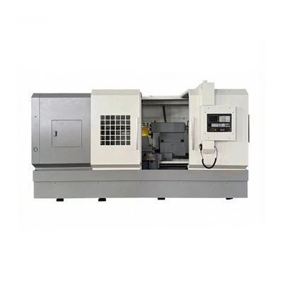
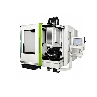
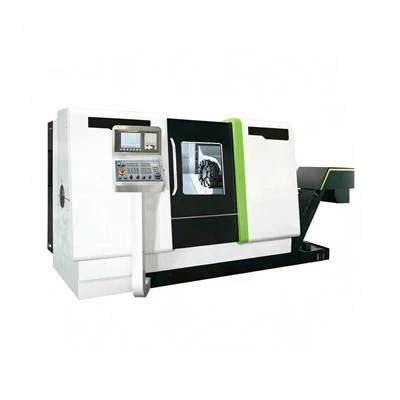
The C and C milling machine is a three-axis CNC milling machine with manually changed cutting tools. It is used for prototype plates, simple pockets, small aluminum components and instructional machining in toolrooms, repair workshops, training centers and short-run production.

Key Features
Two Table Sizes for Compact Parts
The smaller machine has a 600 × 300 mm table and the larger version an 800 × 400 mm table. On small fixture plates requiring multiple drilled holes and milled slots, the selected working surface accommodates the part and clamps without an oversized industrial table.
BT30 or BT40, 6,000 rpm Spindle
Both configurations use BT30 or BT40 tooling and a stated maximum spindle speed of 6,000 rpm. In machining aluminum instrument brackets, the selected taper accepts standard end-mill holders while the available spindle speed covers common light milling operations.
Ball-guide Axis Control
Ball-type linear guideways and a published positioning accuracy of ±0.01 mm support programmed light cuts. On a short run of plastic instrument covers, the axes repeatedly locate pocket and hole coordinates without manually measuring every feature between parts.
Custom C and C Milling Machine
The machine is specified from the component drawing, vise footprint and required axis reach. We set the table, spindle and basic control package around the cutting program, with manual tool-change access retained for low-volume operations.
Customizable Items
• Worktable footprint
• X/Y/Z travel selection
• Spindle toolholding interface
• CNC controller and handwheel
• Vise and fixture layout
• Coolant and chip tray
• Machine enclosure
• Power supply and paint finish

Technical Parameters
|
Parameter |
Small Model |
Medium Model |
|
Table Size (mm) |
600 × 300 |
800 × 400 |
|
X-axis Travel (mm) |
600 |
800 |
|
Y-axis Travel (mm) |
300 |
400 |
|
Z-axis Travel (mm) |
400 |
500 |
|
Spindle Taper |
BT30 / BT40 |
BT30 / BT40 |
|
Spindle Speed (rpm) |
6000 |
6000 |
|
Auto Tool Changer |
None (Manual Tool Change) |
None (Manual Tool Change) |
|
Guideway Type |
Ball Linear Guideways |
Ball Linear Guideways |
|
Table Load Capacity (kg) |
≤400 |
≤400 |
|
Positioning Accuracy (mm) |
±0.01 |
±0.01 |
Quality Control
The ball-guide assemblies and axis reference positions are checked before spindle alignment. The table is inspected for level and movement consistency at the edge of the programmed cutting envelope.
Test operations include face milling, slot cutting and drilled-hole location on a sample plate. Finished dimensions, control functions and protective electrical circuits are examined in the final full-machine inspection.
FAQ
Q: How long does a standard order take?
A: Approximately 1 month.
Q: Can a paid prototype part be supplied?
A: Yes.
Q: What is the maximum specified table load?
A: 400 kg.
Q: What is the Z-axis travel of the larger model?
A: 500 mm.
Hot Tags: c and c milling machine, China c and c milling machine manufacturers, suppliers, factory, C and C Milling Machine, cnc machine tools, Computer CNC Machine, Large CNC Lathe, Machine Tool With Linear Guideways, Rolling element Guideways