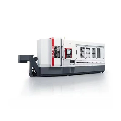
Product Overview
The Lathe Gantry Manipulator is an overhead, three-axis workpiece-handling unit for CNC turning cells. It transfers blanks and finished parts between loading positions, lathe chucks and collection points, and is used in automated turning of automotive components, small shafts and other repeat-production metal parts.

Key Features
Overhead Structure Keeps Machine Access Clear
The 2400 × 1100 × 2800 mm assembly is installed above the turning area, combining high-strength aluminum profiles with welded square-tube support. When lathes stand close together and operators need access to doors, chip bins and service aisles, overhead travel leaves the floor beside the machines available for normal operation.
Three-Axis Reach Across the Turning Cell
Effective travel of 1750 mm on X, 750 mm on Y and 900 mm on Z covers the horizontal transfer path and vertical chuck approach. During transfer between a feed position and a machine spindle, each axis follows its programmed route, eliminating the need to reposition a floor-mounted handling device between successive picks.
Two Workpieces in a Single Handling Sequence
The twin-pick arrangement carries 3 kg × 2, allowing two parts to be collected in one transfer sequence. On short-cycle turning jobs with separate raw-part and finished-part positions, this permits a coordinated exchange rather than two independent journeys of the gantry.
Controlled Placement and Vertical Holding
Repeat positioning is rated at ±0.1 mm for returning to a taught loading point. The Z-axis also incorporates a mechanical locking device: if unexpected downward motion occurs during a raised-part transfer, the mechanism restrains the vertical slide instead of relying only on the drive command.
Customization
Custom Lathe Gantry Manipulator
The gantry layout is engineered from lathe drawings, chuck center height, door clearances, part mass and the required pick-to-place sequence. We configure the axis envelope, gripper and machine-interface logic around the production cell, then build and check the unit against the approved motion layout.
Customizable Items
• Machine-to-machine span
• X / Y / Z travel
• Overall gantry dimensions
• Gripper finger profile
• Single / dual pickup arrangement
• Workpiece flipping orientation
• Chuck interface and I/O signals
• Loading tray / outfeed position
• Controller and alarm logic
• Protective guarding

Technical Parameters
|
Parameter |
Specification |
|
Machine Size (mm) |
2400 × 1100 × 2800 |
|
X-axis Effective Stroke (mm) |
1750 |
|
Y-axis Effective Stroke (mm) |
750 |
|
Z-axis Effective Stroke (mm) |
900 |
|
Repeat Positioning Accuracy (mm) |
±0.1 |
|
Load Capacity |
3kg × 2 |
|
X-axis Theoretical Speed (m/min) |
90 |
|
Y-axis Theoretical Speed (m/min) |
60 |
|
Z-axis Theoretical Speed (m/min) |
90 |
|
X-axis Drive Type |
Gear and Rack |
|
Y-axis Drive Type |
Timing Belt and Pulley |
|
Z-axis Drive Type |
Gear and Rack |
Quality Control
Frame members, mounting interfaces and guideway seats are checked during assembly. Operators complete process-level self-inspection, followed by cross-checks of the installed drive components and the travel clearances at both ends of each axis.
The completed unit is exercised through its loading sequence with the specified workpiece geometry. Inspection covers pickup and release alignment, the Z-axis holding function, end-position sensors and the interaction of machine-ready signals with the gantry cycle.
Before packing, every machine undergoes final inspection of moving parts, fasteners, control functions and exterior protection. Inspection responsibilities are assigned by operation, and independent third-party verification can be arranged before shipment.
FAQ
Q: What is the standard production lead time?
A: Approximately 1 month for the standard configuration.
Q: What are the payment terms?
A: 30% deposit; balance paid before delivery.
Q: What are the theoretical travel speeds of the three axes?
A: X and Z: 90 m/min; Y: 60 m/min.
Q: Which transmission is used on each axis?
A: Rack-and-pinion on X and Z; timing belt and pulley on Y.
Hot Tags: lathe gantry manipulator, China lathe gantry manipulator manufacturers, suppliers, factory, Auto Turning Machine, Automatic Drilling and Tapping Machine, Automatic Grooving Machine, Automatic Loading and Unloading Machine, automatic machine tools, Automatic Production Line